How to Build an RPU Board
Get a Printed Circuit Board (PCB)
Technically, you don’t need a PCB to build an RPU board. Each time I’ve made a version of RPU, I built the prototype by hand. But with the latest revisions, you’ll have to run dozens and dozes of wires between sockets in order to make it work. I recommend just getting a PCB printed, or buying a kit. First, you’ll need to decide which revision you want. Here’s a list of MPU boards and which RPU will work with them:
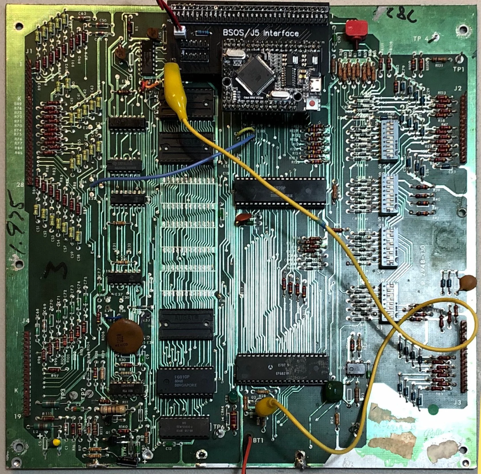
Bally -35 with a Rev 3 (note the jumper wire to the top leg of R134)
Bally original AS-2518-17 or -35 MPU will work with a Rev 4 (plugged into J5) or a Rev 102 (plugged into the CPU socket)
If you have a Bally machine with an original MPU, a Rev 4 board will work fine plugged into J5, but the J5 connector doesn’t include the interrupt (IRQ) line. For that, you’ll need to run a jumper from the RPU board down to the top leg of R134 (just below U11). If you use a Rev 102 instead (which plugs into the CPU socket), you won’t need the jumper wire.
Stern MPU-100 or MPU-200 will work with a Rev 4 (plugged into J5) or a Rev 102 (plugged into the CPU socket)
Many early Stern machines have a sound card already plugged into J5 of the MPU. The Rev 4 RPU board mirrors the J5 on the top, so you can plug the Rev 4 into J5 and then the sound board connector into the RPU. If you have a MPU-100, you’ll have to run a jumper wire down to the top leg of R134 to pick up the IRQ signal. If you use a Rev 102 (plugged into the CPU socket), then you won’t have to mess with the sound board connector or the jumper wire.
Alltek with a Rev 102
Alltek Ultimate MPU will work with a Rev 4 (plugged into J5) or a Rev 102 (plugged into the CPU socket)
The Alltek works great with a Rev 4 or Rev 102. There are no jumpers required for the IRQ line—the RPU board gets everything it needs from J5 or the CPU socket.
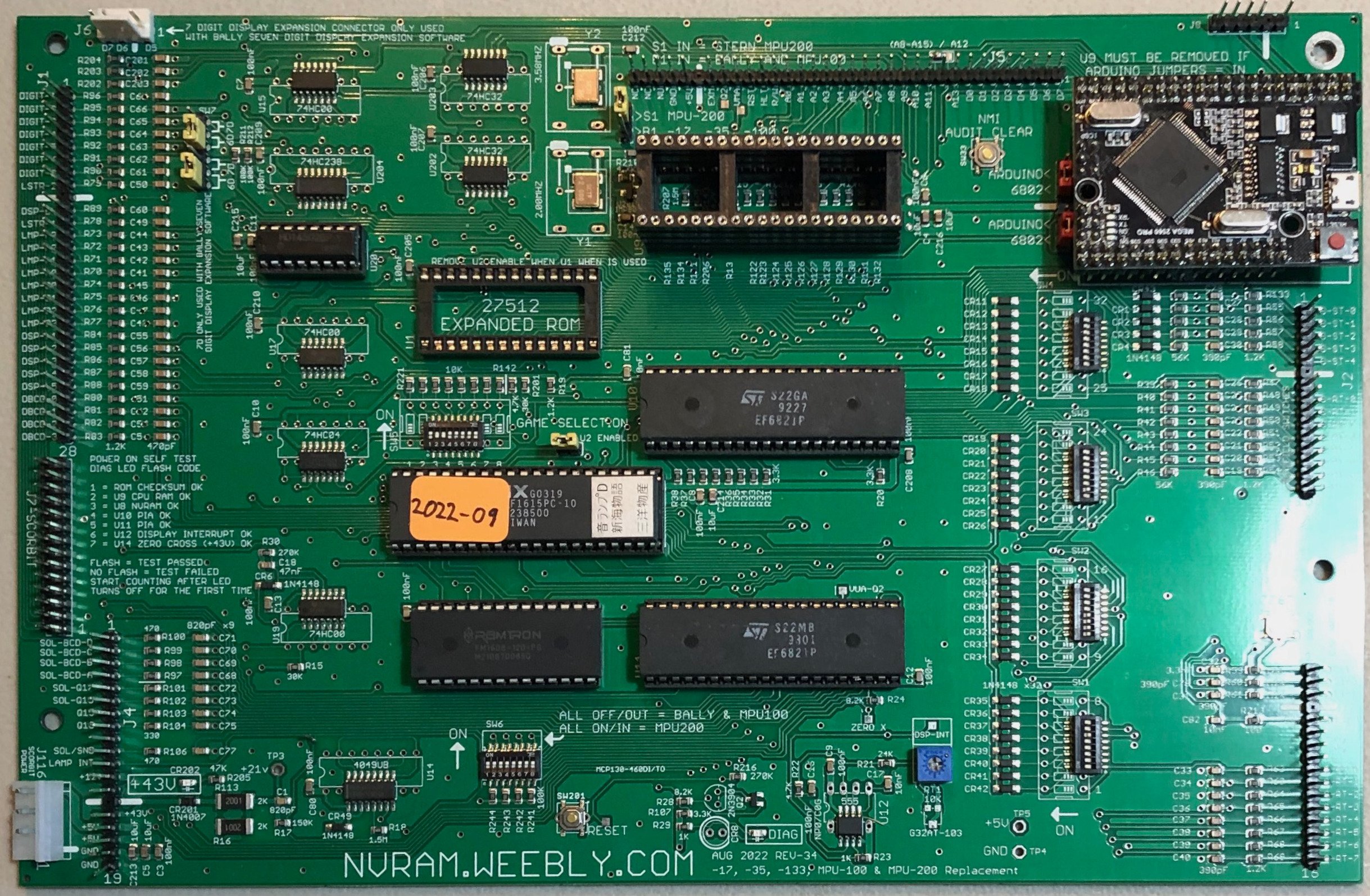
Weebly with a built-in Arduino socket
Weebly MPU will work with a Rev 102, but the newer Weebly's already have an Arduino socket
The early Weebly MPUs will not work with a Rev 4 board plugged into J5, but they work fine with a Rev 102 plugged into the CPU socket. The newer Weebly’s have an Arduino socket right on the MPU. These work fine (adjust your jumpers as per the Weebly documentation), but you won’t be able to dual boot your pinball machine if you use the built-in Arduino socket. In order to use the Arduino, Weebly requires that you remove your original CPU, and that means you can’t boot to it until you put it back in.
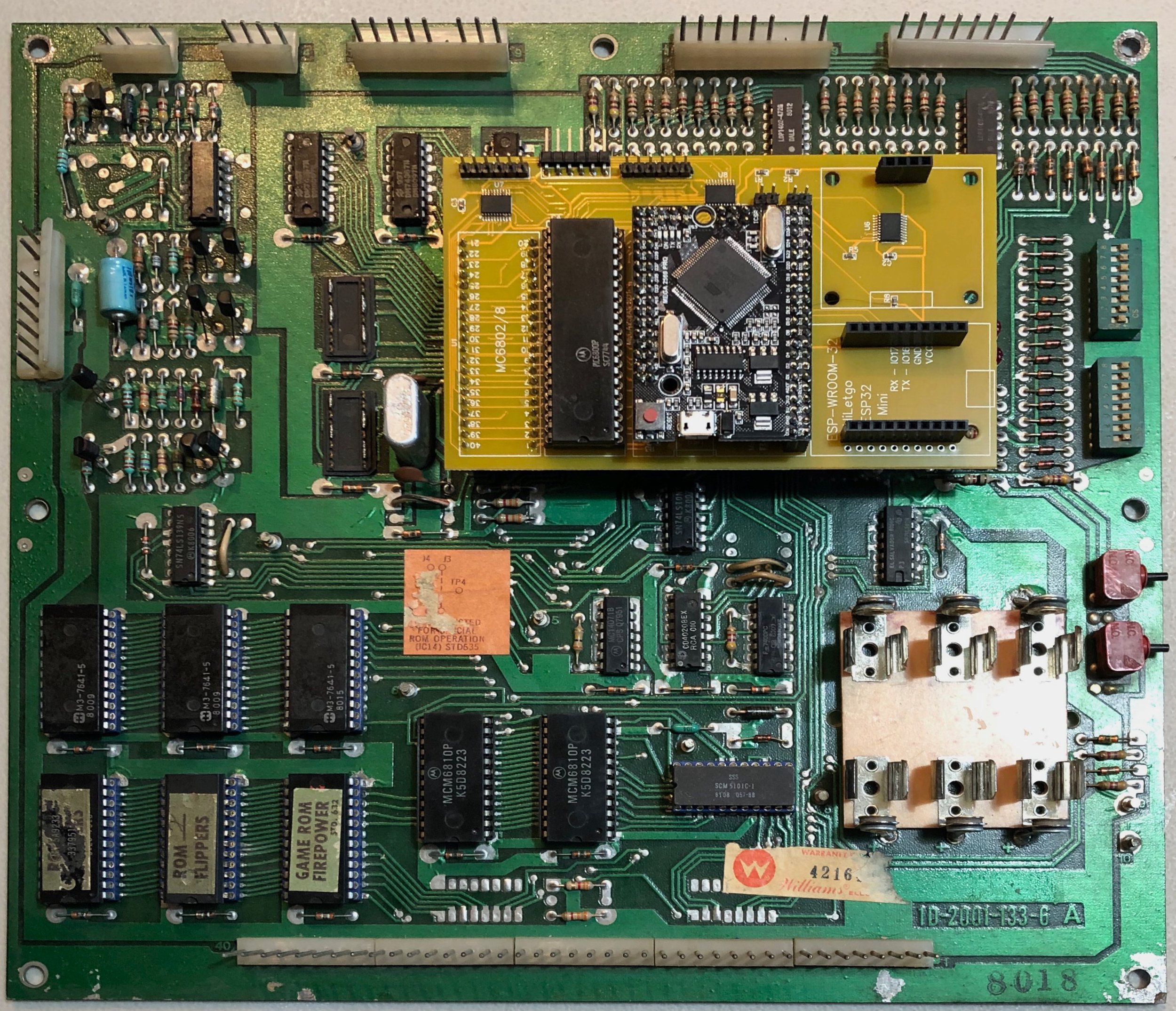
System 6 with Rev 102
Williams System 4-11C works with a Rev 102
All the early Williams MPUs work the Rev 102.
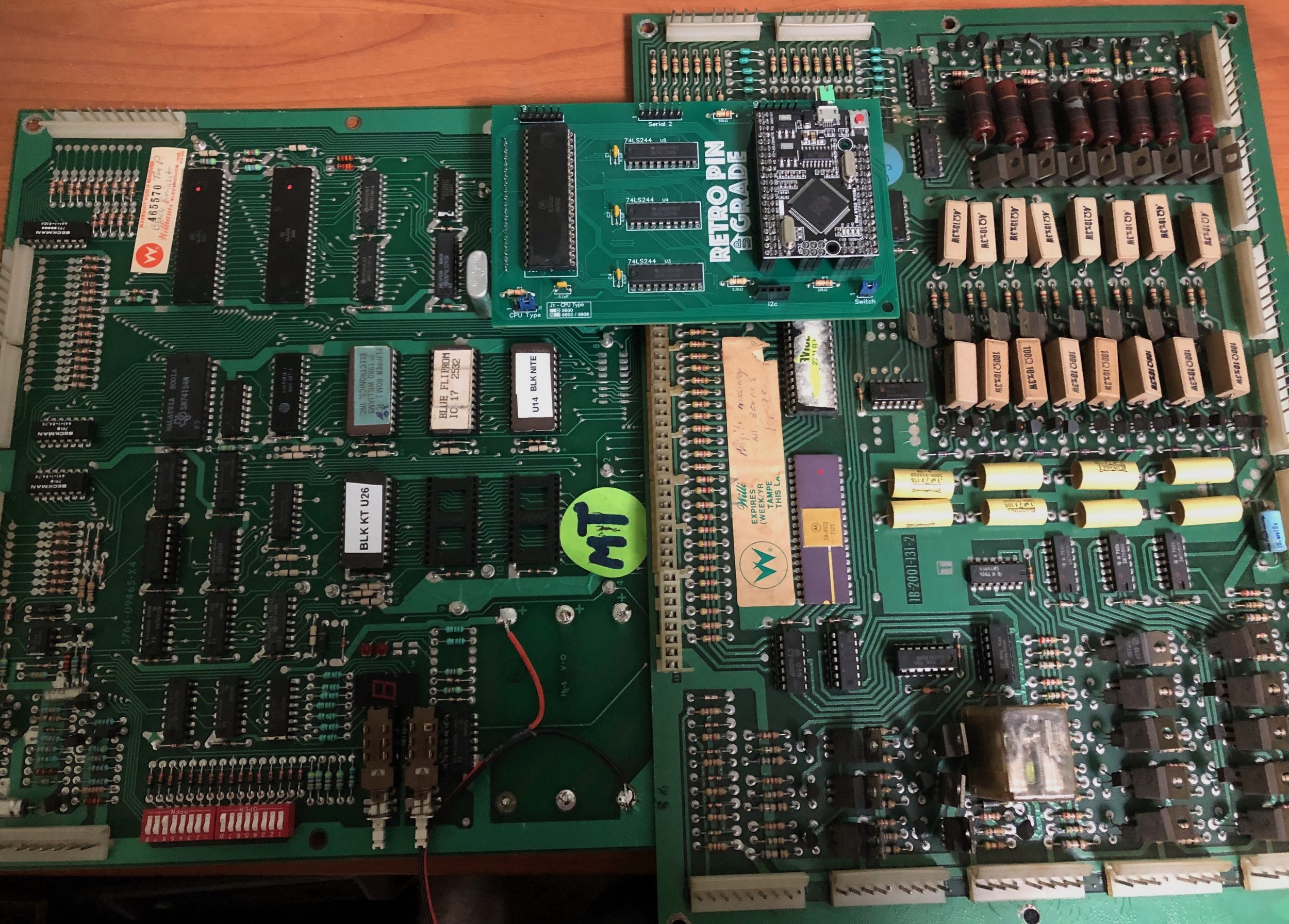
System 7 with Rev 101 (note how Rev 101 overlaps the driver board)
Make sure you orient the Rev 102 properly on the board (pins lined up with CPU socket so that pin 1 matches pin 1). With the System 7, you need to use a couple of CPU sockets in order to space the Rev 102 off the MPU board enough so that it clears the big connector at the bottom of the board.
With the System 9 boards and up, there are multiple 6802/8s on the board (one for game and one for sound). Be sure you’re plugged into the correct one.
Atari
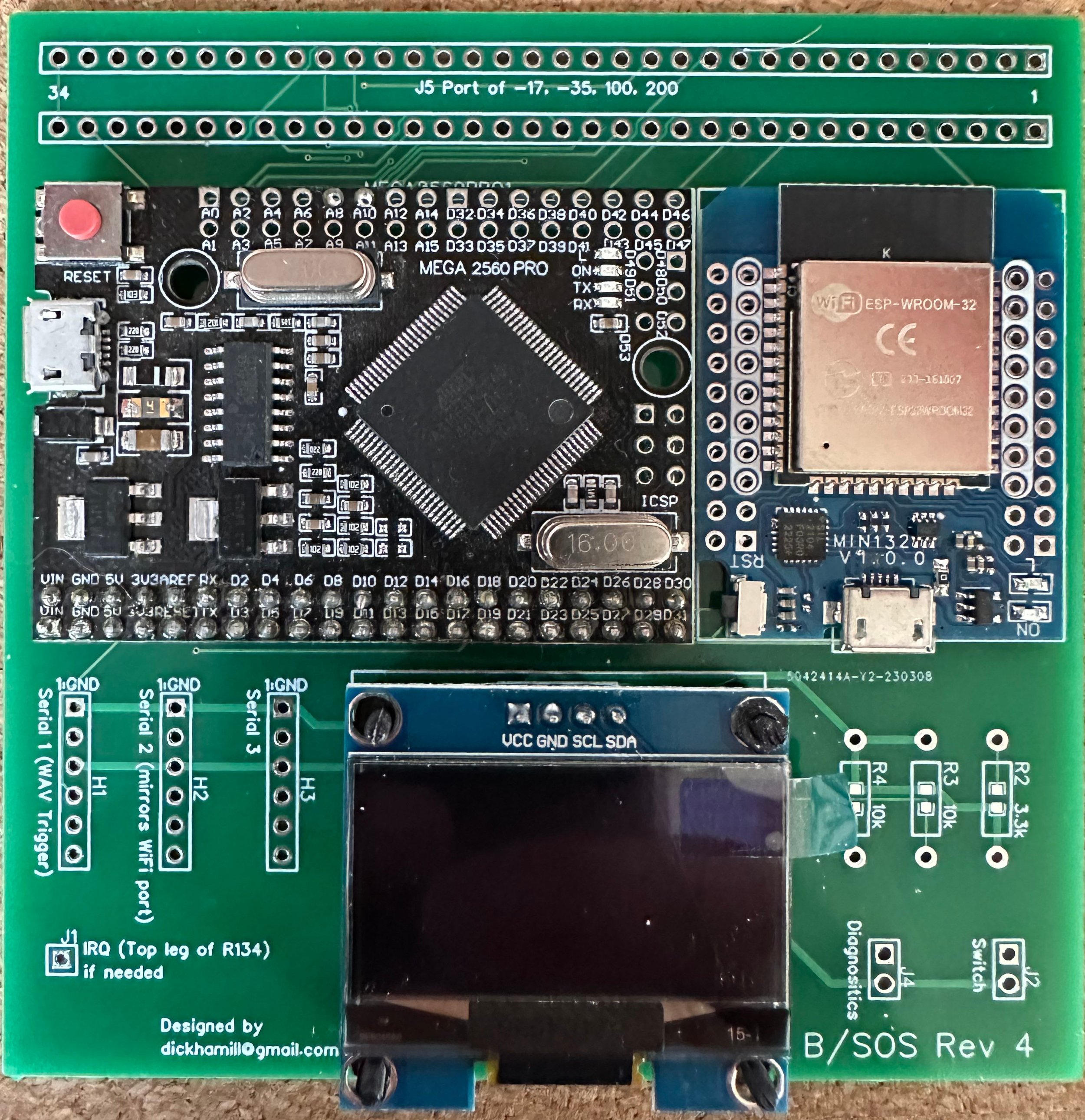
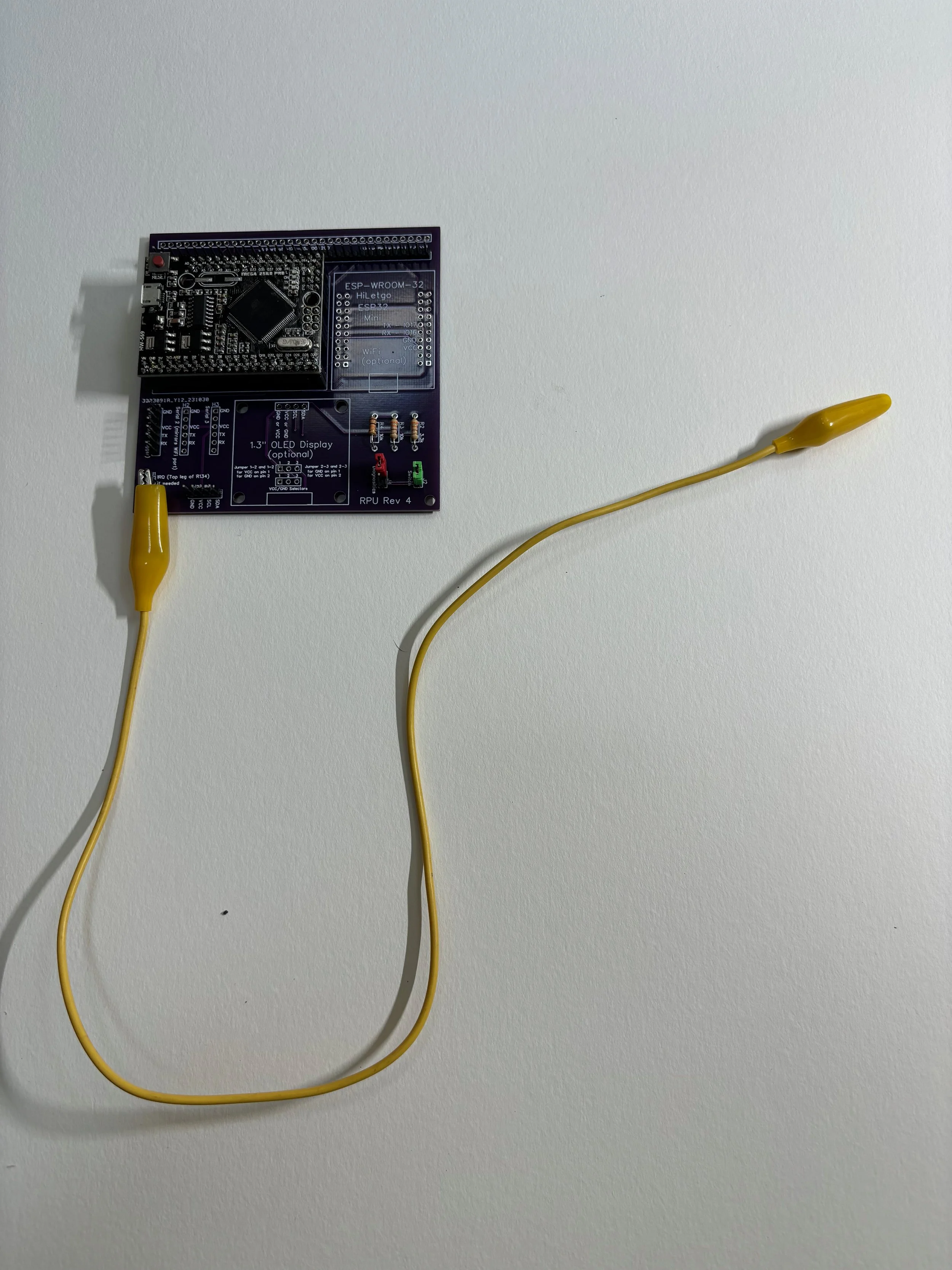
Rev 4 with optional Wifi and display
The Atari MPUs work with the Rev 102. At the time of this writing, I haven’t published a library for Atari.
Gottlieb System 80
The Rev 103 RPU board might support Gottlieb.
Game Plan
The Rev 200 RPU board will support Game Plan
Once you know which Revision of the RPU you need, you can find all the schematics and Gerber files here:
https://github.com/RetroPinUpgrade/ExampleMachine/tree/main/Schematics
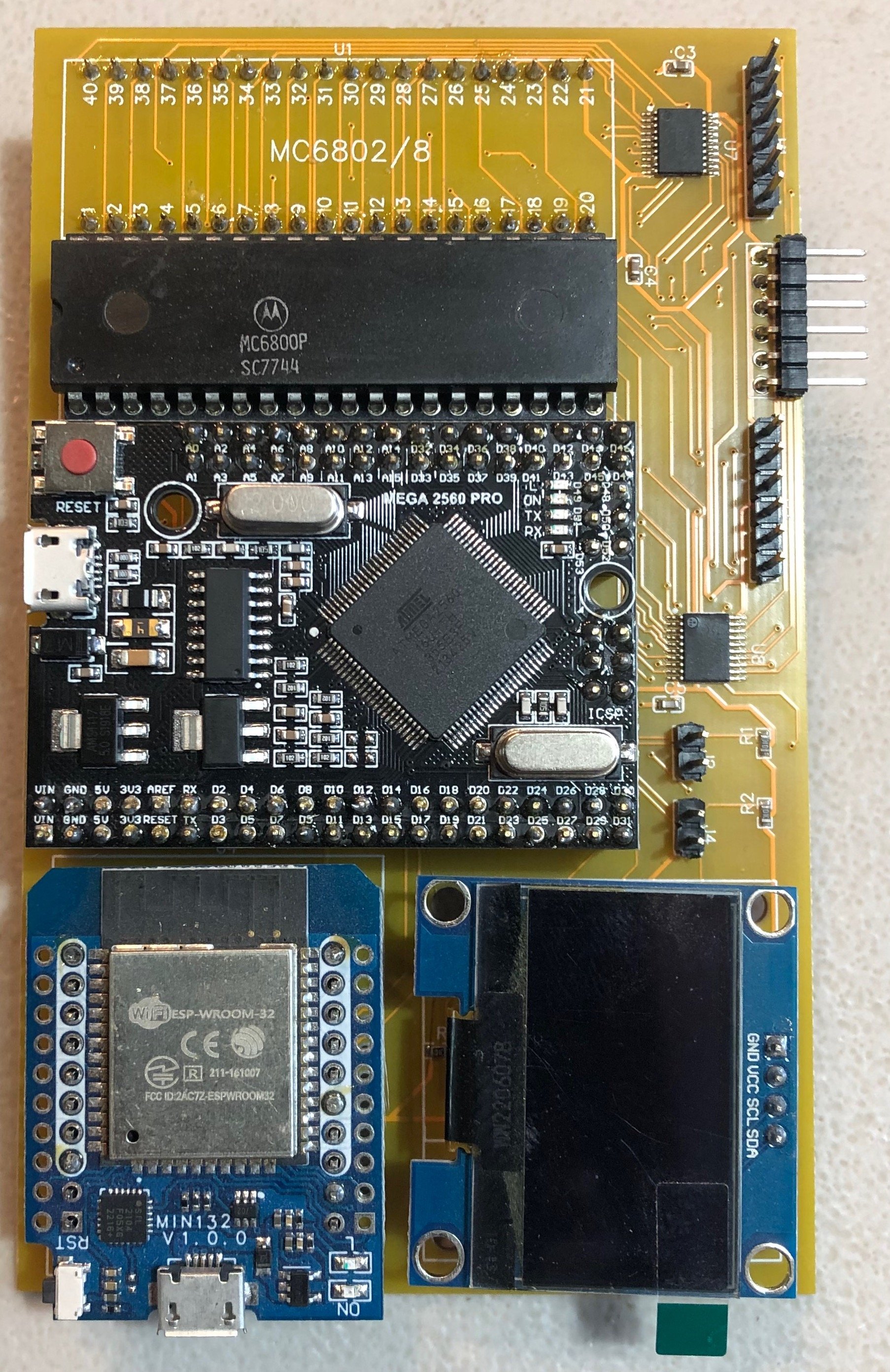
Rev 102 with optional Wifi and display
If you’re wiring up your own board, just make the connections according to the schematics and good luck! If you want to order PCBs, grab the Gerber zip files and use one of the services. So far, I’ve used JLCPCB (the shipping costs more than the boards, but they’ve worked fine). In the future, I plan to give PCBWay a shot. I’ll write a blog post on that experience. The process of ordering a Rev 4 is very simple. Just upload the Gerber, accept all the defaults for thickness and such, and order. You’ll get a decent deal on 10 boards or more, but less than that and you’re paying a bunch per board for shipping.
To order the Rev 102, you have to upload a BOM and CPL file because there are surface mount parts on it. I put instructions on the GitHub site. If you prefer a through-hole board (with chips you solder yourself) then you can try the Rev 101. The Rev 101 makes you choose your CPU type with a jumper and it doesn’t have good connectors for newer peripherals, so I recommend the Rev 102.
Get parts
Depending on the Revision of RPU board you’re building, you’ll need different parts.
Rev 4
Male Headers
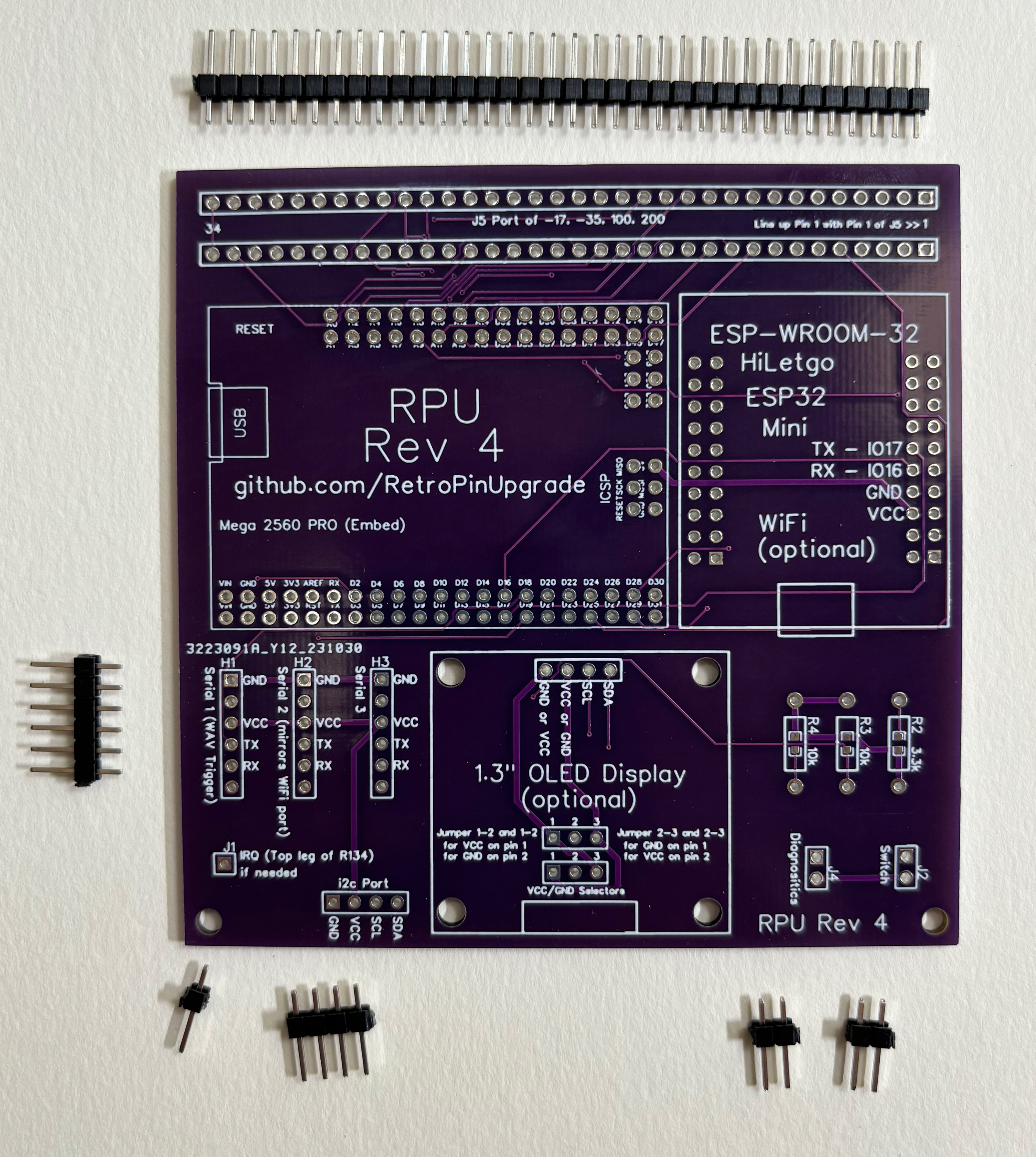
The Rev 4 uses a single row of header pins (2.54mm or 0.1” pitch) to mirror the J5 port in case the machine has a sound card plugged in to that connector normally. I usually install a 34 pin connector there regardless of the MPU board. Older boards only have a 32-pin J5 connector. Bally later had a 33 pin and Stern went to 34. They’re all compatible—the extra pins don’t cause issues.
The Rev 4 also has headers for a couple of options & peripherals. There’s a single pin pad for a connector for the top pin of R134 on older boards. You can also have a header for a WAV trigger or i2c peripheral. All these header pins are 2.54mm or 0.1” pitch, and single row.
I recommend buying a big bag of header pins and cut them down as needed.
Bag of header pins from Amazon
Recommended Male Headers cuts:
34 pin for J5 mirror (top)
6 pin for H1 (WAV Trigger)
1 pin for IRQ (lower left, not needed on MPU-200 or Alltek)
4 pin for i2c port (only needed for peripherals like the Accessory Lamp Board)
2 pin for diagnostics
2 pin for boot switch
Cut down a 40 pin
Female Headers
For the J5 connector, you’ll need a single row, 34 pin, 2.54mm (0.1”) pitch female connector. Only the Stern MPU-200 and the Alltek have 34 pin headers for J5. For the -35, you only need 33 pins, and for the -17 or -100 you only need a 32 pin. The header is keyed at pin 29, but I usually cut down my header so that I only have the number of pins I need for the given MPU board. You can build your RPU to suit your needs or give it a 34 pin connector for maximum flexibility.
Buy a bag of 40-pin Female headers and cut them down
The Arduino requires 4 double-row female headers. They are 2x21 pins, 2x3, 2x3, and 2x16 (for a grand total of 86 pins). 3M makes really good double-row headers but they are expensive. An alternative is to just buy a big pile of single-row headers, cut them to length, and make it work that way.
For the Arduino, you can either cut down 40-pin Female headers, or you can get double-row headers from 3M (more expensive, but clean). You’ll need the following:
Qty 2 - 16x2 headers
Qty 2 - 3x2 headers
Qty 1 - 5x2 header
Female headers for the WiFi module are optional.
Female headers for the OLED display are optional.
Resistors
You need 3 resistors for this project. Two 10 kOhm and one 3.3 kOhm. Here are some links to Digikey:
Jumper (shunt) Caps
If you want a selector for your diagnostics pins, or a way to set your boot switch, you can get these jumper caps (they’re also called shunts). I got an enormous bag from Amazon at one point.
Jumper Wire
Except on the Stern MPU-200 and Alltek replacement, the Rev 4 will need a jumper wire to pick up the IRQ signal. This is accomplished with a clip to the top lead of R134 on the MPU.
Switch Wire (for optional boot switch)
If I’m going to have a physical switch for the boot switch, I like to put a locking connector on the board with mating leads off to a switch. Amazon has a bag of 20 that work pretty well. The pitch of the connector is only 2mm (the holes in the PCB are 2.54mm), so it’s a tight fit but works well.
Sound (sometimes optional, but always recommended)
WAV Trigger - this is a sound card made by RobertSonic
Rev 102
Male Headers
Cut down 40-pin Male headers (2.54mm or 0.1”) - Bag of header pins from Amazon
6 pin for H1 (WAV Trigger Connection)
2 pin for diagnostics jumper
2 pin for boot switch jumper
Female Headers
Cut down 40-pin Female sockets (2.54mm or 0.1”) - Bag of sockets from Amazon
OR, get these double-row 3M ones which are cleaner and more expensive
Qty 2 - 16x2 headers
Qty 2 - 3x2 headers
Qty 1 - 5x2 header
IC Pins
You’ll need a total of 40 pins (Qty 2, 20x1) of IC pins. These aren’t your normal 2.54mm or 0.1” header pins because they’re round instead of square and they’re meant to plug into IC sockets.
IC Sockets
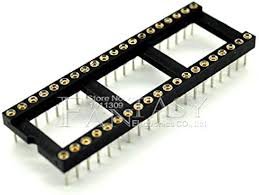
You need at least one socket, but buy 4.
Jumper (shunt) Caps - big bag from Amazon
Switch Wire (optional) - locking connector and short leads
Sound (sometimes optional, but always recommended)
WAV Trigger - this is a sound card made by RobertSonic
Solder
Soldering Rev 4
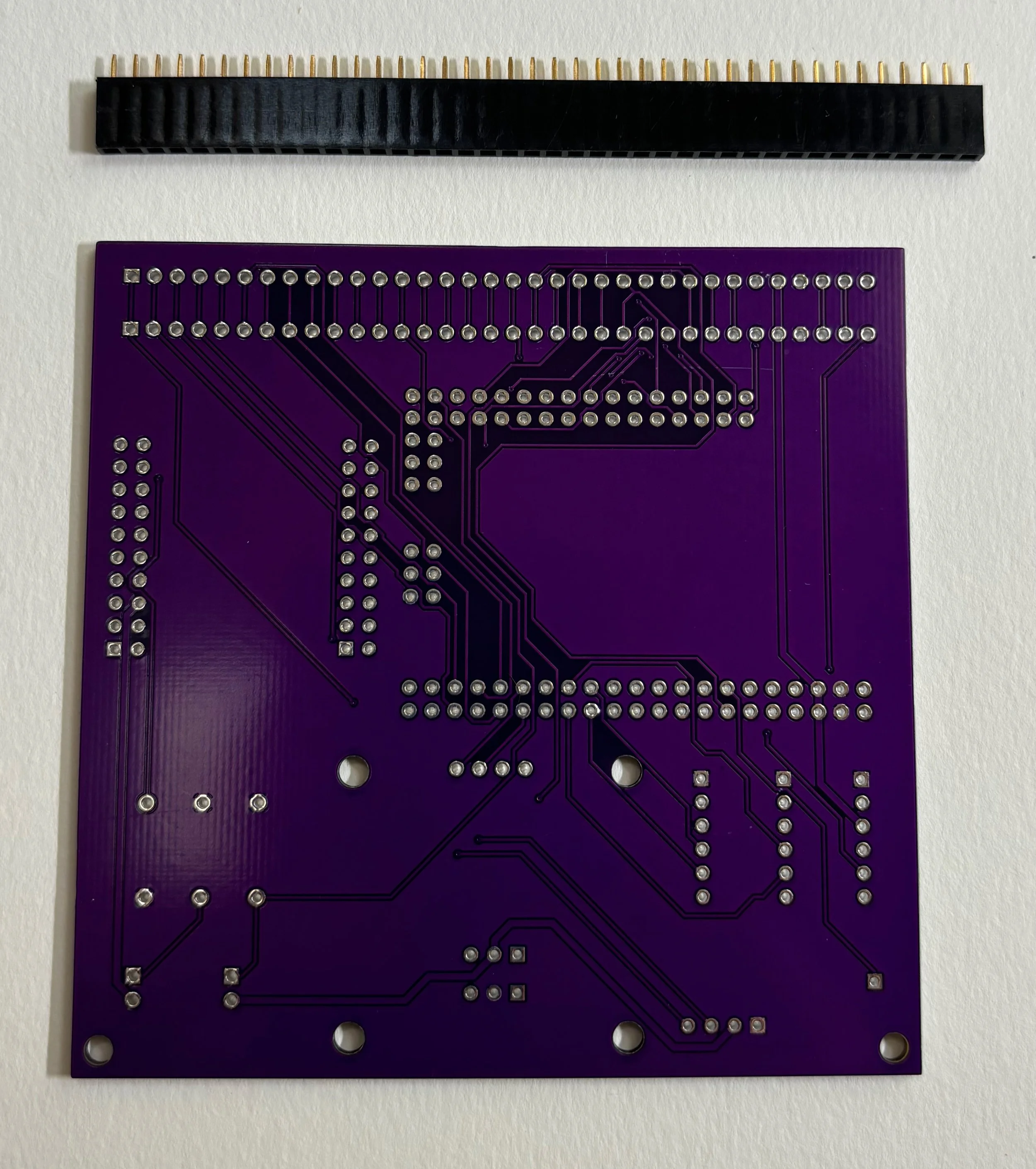
34-pin F header on back of Rev 4
Rev 4 soldering is straightforward. Only one component gets placed on the back of the board (soldered on the top side), and that’s the Female header that’s going to plug into the J5 connector of the MPU. If you’re plugging into a Bally AS-2518-17, or Stern MPU-100, your Female connector only needs 32 pins. The Bally AS-2518-35 board has 33 pins for J5, and the Stern MPU-200 has 34. The Alltek replacement MPU has 34 pins. So, you can cut your header down to the appropriate size (32, 33, or 34 pins), or you can make your Female connector 34 pins and just hang the extra pins off the left side. I usually build my boards with 34 pin Female connectors in case I ever upgrade the MPU to an Alltek.
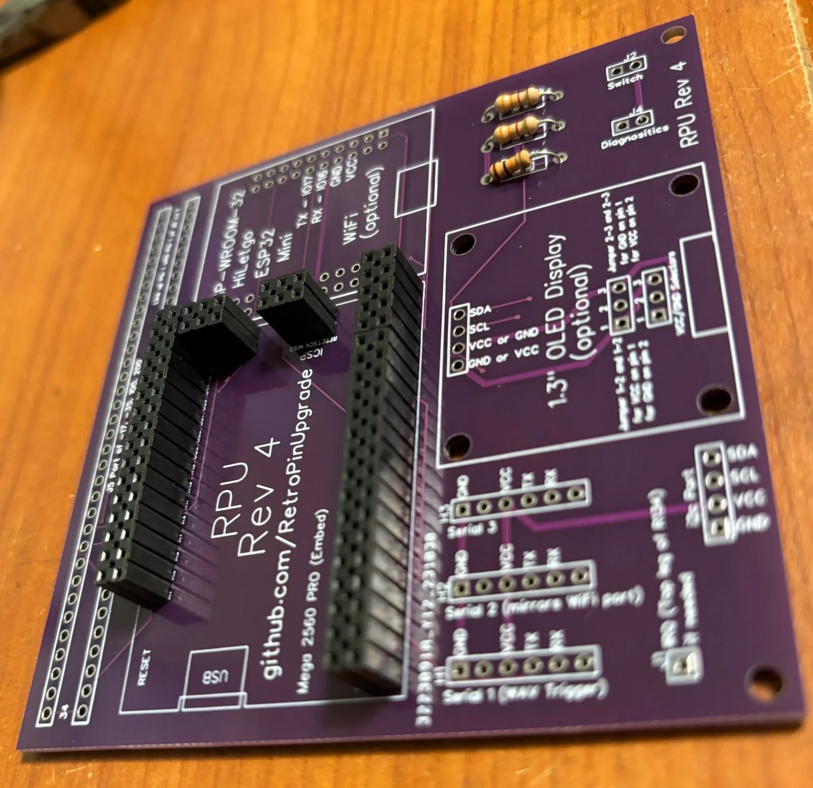
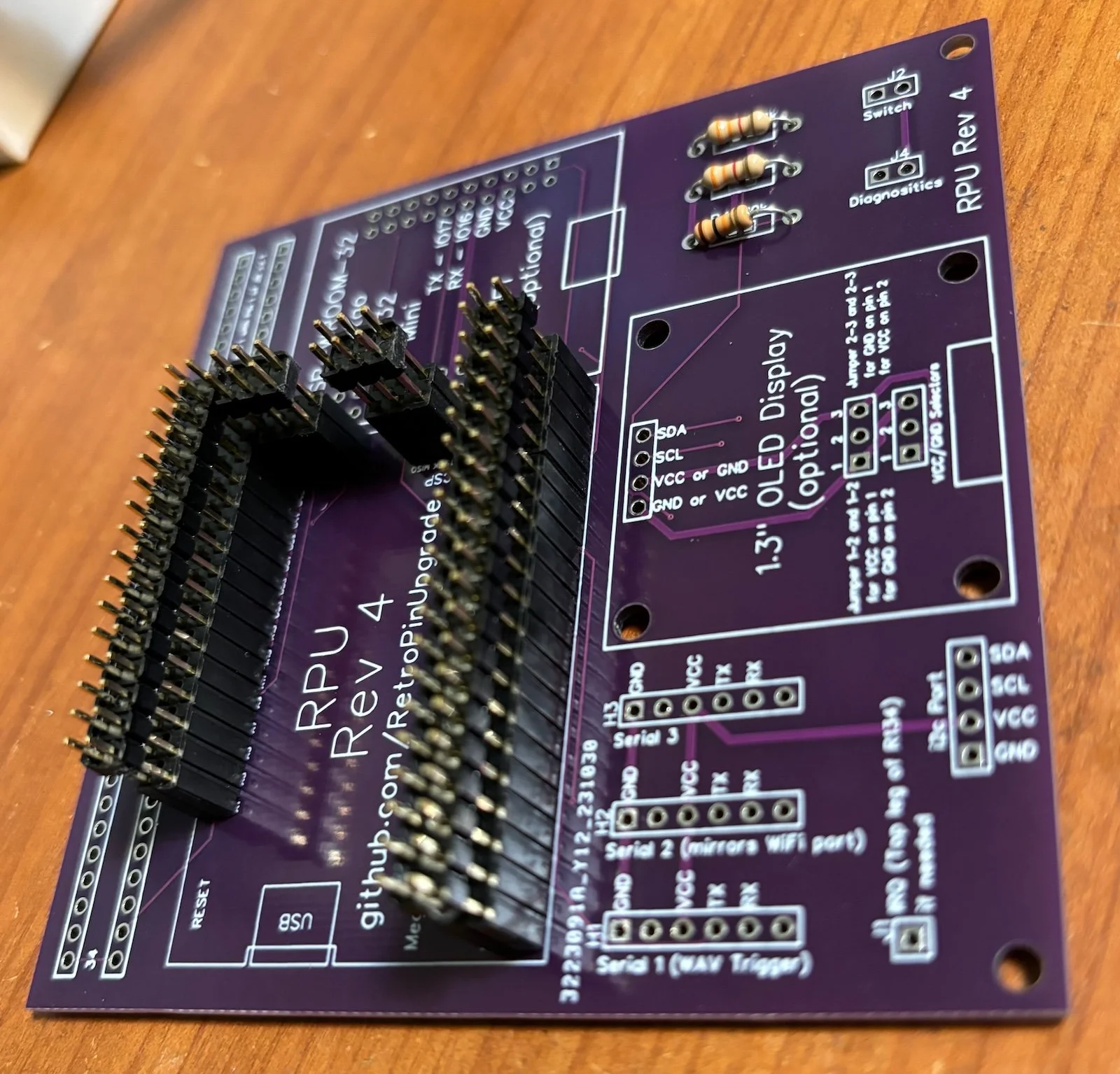
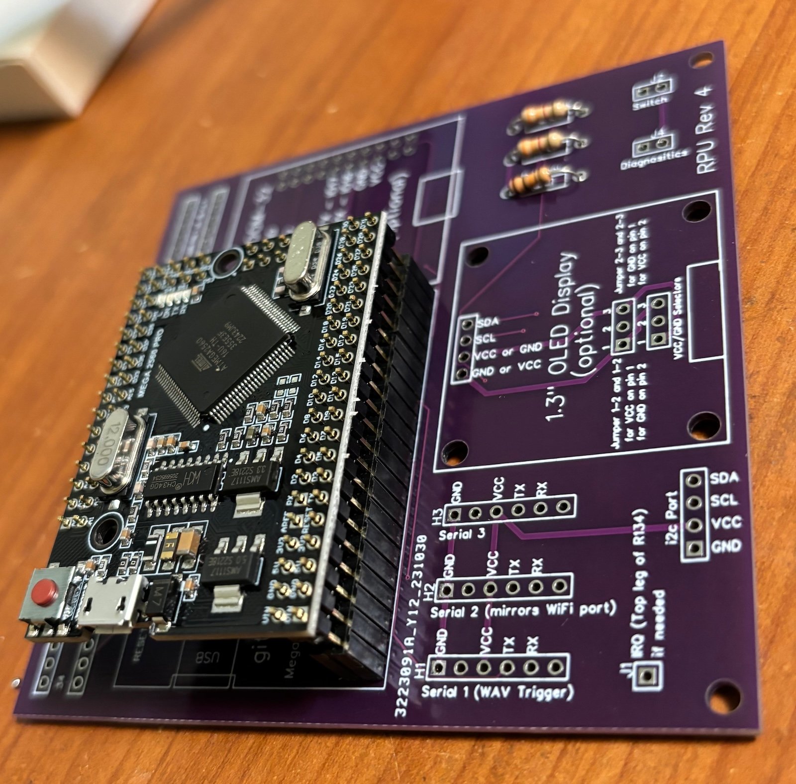
Next, you can put the double-row Female headers on the board and then insert the Male pins for the Arduino. With the entire thing “dry fit” it’s easy to make sure it all lines up while you solder the pins on the top side of the Arduino. Then you can flip the board and solder the headers.
Double-row Female headers dry fit
Place Arduino pins in headers
Solder Arduino pins in place to ensure alignment
With the Arduino and Female headers installed, the bulk of the remaining soldering is the Male headers. Install a big row across the top to mirror the J5 port up (this is used for Stern machines with sound cards plugged into J5). The serial port (for WAV Trigger), i2c, and others can be soldered as needed. If you’re installing on a MPU-200 or Alltek, you don’t need the single-pin connector for the interrupt (IRQ) because the board will pick up that signal from pin 34 of J5.
Above, I mentioned an optional locking switch wire. If you want to mount a physical switch to choose between original code and new code, you would solder that locking switch port to J2 (lower-right corner of this board). For home use, I usually just put a 2-pin header there and install a jumper. In software, you can configure your machine to boot to original code if you hold down the Credit/Reset button while you boot. But perhaps a physical code-choice switch (mounted inside the coin door) would be useful on location.
Male headers
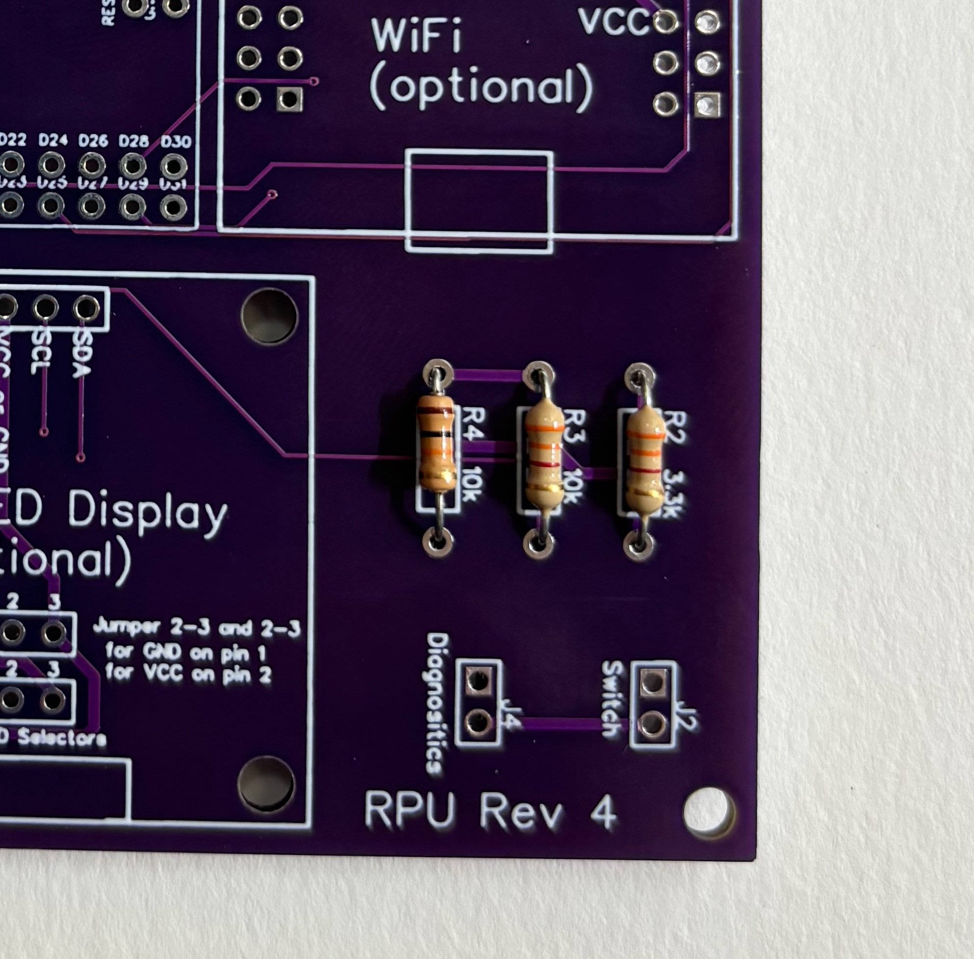
Finally, finish off the board with the resistors. There are a couple of optional parts you could add (OLED display and WiFi board). Those ports have been tested, but not much code has been written for them at this time (Fall, 2024).
R2 is a 3.3kΩ
R3 is a 10kΩ
R4 is a 10kΩ
If you zoom in on these pictures, you might notice that I have two 3.3kΩ resistors and one 10kΩ. Why is that? I don’t know. I also don’t remember what happened to R1, but that label is totally not used on this board. It’s those little quirks that give this board so much “character.” Enjoy!
Resistors
Resistors installed
Soldering Rev 102
When soldering the Rev 102, I usually start with the machine pins on the back. These pins are going to plug into the MPU’s processor socket. Use an extra 40-pin socket to align the two rows of 20-position machine pins.
Row of Machine Pins (round)
Pins and socket
Placed on bottom
Next, I solder the Female headers for the Arduino and the socket for the original CPU. If the headers are wobbly in the board, I’ll put the headers, pins, and the Arduino all together in a stack so that everything lines up for soldering.
Finally, I’ll add the Male headers for the Serial port, Diagnostics jumper, and Switch. There are other optional spots for peripherals, like the display and WiFi module. Add them as needed.
CPU socket and Arduino headers
Parts in place for soldering
Once you have your board built, you’re ready to upload code and install it on your machine.
